
Start with the wear pattern before you blame the cutter
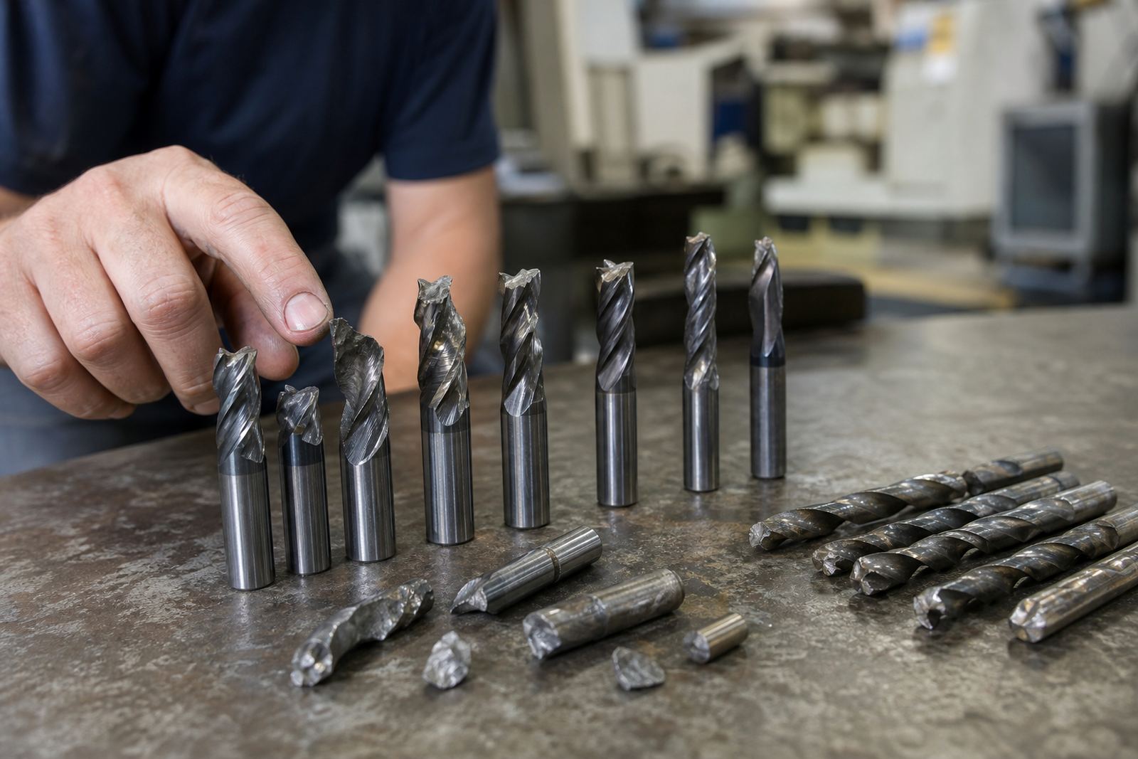
When a solid carbide end mill or drill comes out damaged, the first mistake is to call it a bad tool. In most CNC shops, the tool is simply the part that failed last, while the cause may sit in setup, speed, feed or engagement. A careful look at the damage often tells a more useful story than the scrap bin ever will.
Look for where the damage started. Wear on the flank, chipping at the corners, built-up edge, rubbing on the shank, or breakage just below the flute all point in different directions. A clean snap usually suggests overload or poor rigidity. A tool that looks polished and blunt may have been rubbing, not cutting. If the edge is chipped in one spot only, the cutter may have hit an interrupted cut or the work holding may have shifted.
What edge damage says about speed and feed
Speed and feed mistakes show up fast in carbide. Running too slow can cause rubbing, heat and early dulling. Running too fast, or with too much feed in the cut, can overload the edge and chip it out. The trick is to link the wear to the cutting sound, chip shape and machine load, not just the final damage.
- Blue or straw colouring on chips can point to excess heat and poor chip evacuation.
- Fine powdery chips often suggest the feed is too light and the tool is rubbing.
- Long stringy chips can mean the material is not breaking cleanly or the chip load is too low.
- Sudden corner chipping can indicate a feed spike, vibration, or an interrupted cut.
On stainless, tool life can drop quickly if the feed is too cautious. On mild steel, the opposite problem is common too much spindle speed with a light chip load that just polishes the edge until it goes blunt. In both cases the cutter is telling you that the cutting conditions are not balanced.
Breakage at the shank often means rigidity was the issue
If a cutter breaks near the shank or close to the collet, rigidity should be checked before anything else. Long stick-out, loose clamping, worn holders, or a weak setup can turn a good tool into a short-lived one. This is especially common on deep pockets and long-reach jobs where the tool is already working harder.
Check for chatter marks on the part and tool. A shiny band on the shank can show that the cutter was rubbing against the wall, or that the setup was flexing under load. If the machine is underpowered for the cut, or the job was shifted to a different centre with a different spindle condition, the same programme may behave differently and the tool will pay the price.
- Reduce overhang where possible and use the shortest practical tool length.
- Check holder cleanliness and taper condition before each job.
- Make sure the part is clamped so it cannot lift or twist mid-cycle.
- Listen for vibration at entry and exit, especially on thin walls.
Chip evacuation is a quiet cause of tool failure
Many cutters fail because chips are left in the cut. This is common in deep drilling, slotting, and pocketing in materials that make long chips. When chips recut, the edge gets hit by hot debris again and again, which can wear it down far faster than expected. In humid coastal areas like Durban or Gqeberha, poor chip control can also encourage corrosion on tools that sit idle between runs.
Look at the flute after failure. Packed chips, welded material, or scorched residue point to evacuation problems. That means the issue may be coolant pressure, nozzle position, peck cycle settings, or an engagement strategy that is too aggressive for the material. If the tool is doing fine for the first few parts then suddenly failing, chip packing is a strong suspect.
A Germiston job that showed the real problem
A local example: a CNC shop in Wadeville was losing solid carbide drills on a mild steel component before the first production batch was finished. The team suspected the drill quality, but the failure pattern told a different story. The tip was not crumbling evenly. It was chipping on one lip only, with slight rubbing marks on the body and packed swarf in the flutes. That pointed to a feed imbalance and chip evacuation issue, not a manufacturing fault.
After checking the setup, the job was found to have a slightly off-centre clamping position and a peck cycle that was too shallow for the hole depth. The fix was simple once the cause was clear: improve clamping, adjust the peck depth, and keep the coolant stream aimed properly at the cutting zone. Tool life improved straight away and the shop stopped burning time on repeat failures.
Use failure data to standardise the next run
Tool failure only becomes useful when the information is captured and used. A short note on what failed, where it failed, and under what conditions can save hours later. Over time, this becomes a shop floor reference that helps with new materials, different machines and urgent repeat work. It also helps with stock planning, because you begin to see which tools are being overused and which sizes need backup stock.
A practical failure record should include the following:
- Material type and hardness if known.
- Tool diameter, flute count and length.
- Spindle speed, feed and depth of cut.
- Coolant method and chip clearing method.
- Where the damage appeared on the tool.
- How many parts were completed before wear or breakage.
That information makes it easier to adjust the process, compare runs and order the right replacement tools before production stops.
When to adjust the process and when to change the tool
Not every worn cutter is a process fault, and not every process fault can be fixed by changing the tool. The best outcome comes from checking both. If the wear is predictable and repeatable, the programme may need a better feed, a shorter tool, or a more suitable flute style. If the damage is random, look harder at the machine condition, operator set-up, material consistency and coolant delivery.
For shops across Johannesburg, Pretoria, Cape Town, Durban and Gqeberha, the message is the same: read the tool before the next run. The cutter is often giving you a clear warning. Catch it early and you protect spindle time, parts quality and the bottom line. Ignore it and the same fault usually comes back, only this time it takes the part with it.